

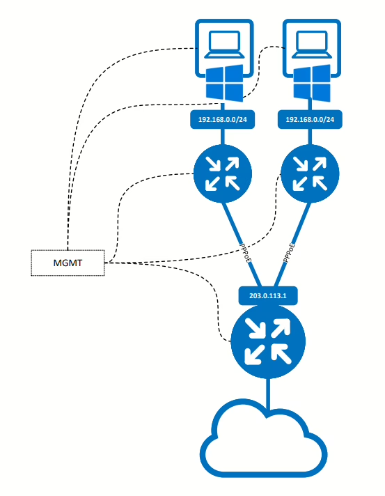
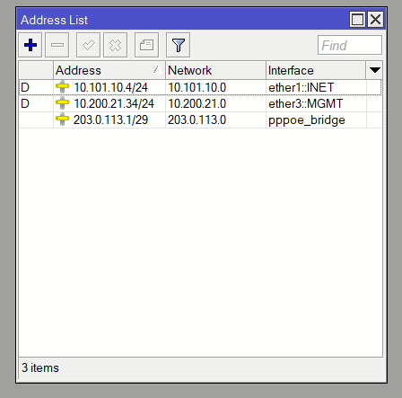
The topology consists of a core router (PPPoE server) and 2 client routers, all Mikrotiks. Then each client router has a single host.
Each router and test PC has an additional interface in the MGMT network however with no gateway set so this is only used to access the devices remotely for testing/demo purposes. The LAN is a bridge with the uplink port within that bridge connecting to the client routers.
| Device | ether1 | ether2 | ether3 |
| PPPoE Router | WAN – DHCP to DEV Network | pppoe_bridge (203.0.113.1/24) | MGMT |
| Client 01 Router | WAN – PPPoE Client | LAN (192.168.0.1/24) | MGMT |
| Client 02 Router | WAN – PPPoE Client | LAN (192.168.0.1/24) | MGMT |
https://www.youtube.com/watch?v=pOHcQuAqvmw
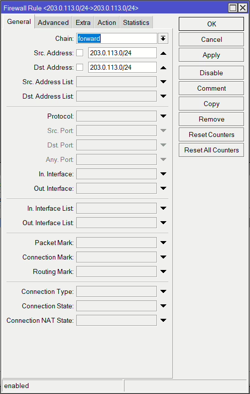
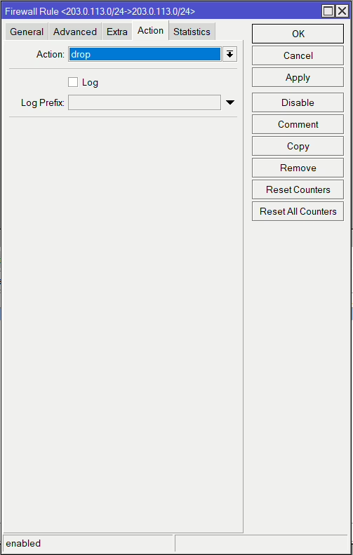
Firewall Filter (forward)
This rule prevents clients being able to communicate between each other on their WAN subnet.
PPPoE Server
On our core server which we are using as the PPPoE server, we add the PPPoE configuration.
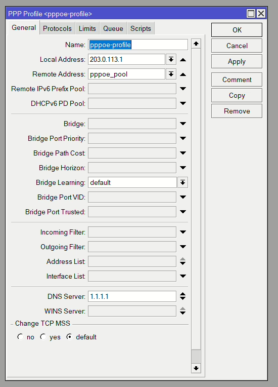
PPPoE Profile
Go to PPP > Profile and add a new one. The profile can be unique or for all clients. If you are using the dynamic Queue feature you may want a profile per speed.
Set the Local IP to the one on the LAN interface of your core router. Optionally, add a DHCP pool for the client’s assessment of IP addresses.
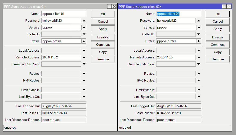
PPPoE Secrets
PPP > Secrets to add the client connection details including username & password and the option to add a static IP to be assigned to the client (if not using the DHCP pool).
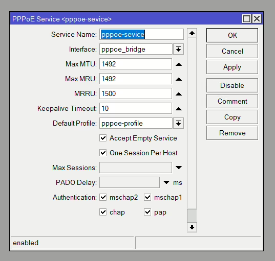
PPPoE Service
Now we enable the PPPoE service by adding a new PPP > Service. Select the LAN interface (in our case the bridge) and the already created profile. We also check One Session Per Host.
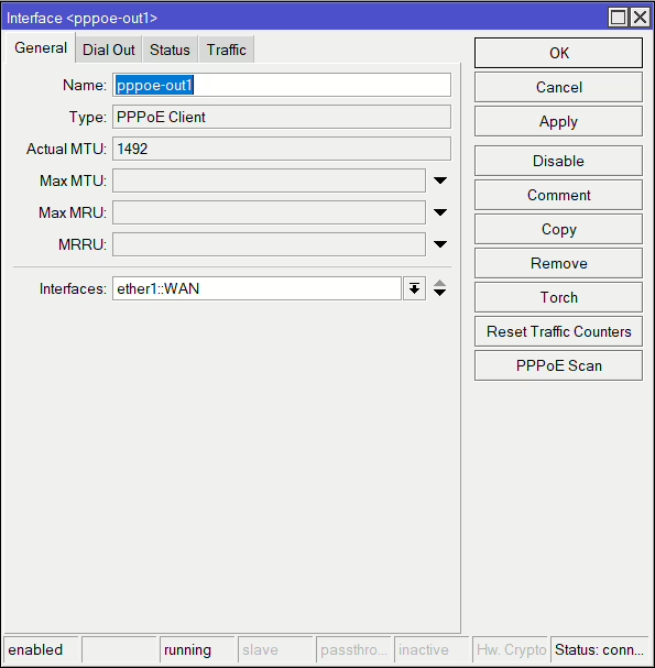
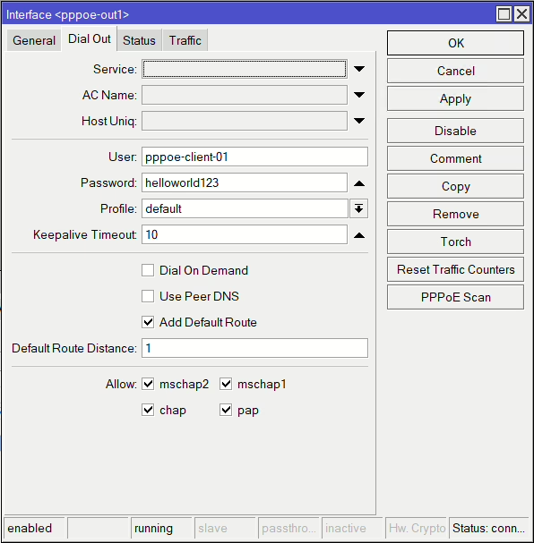
PPPoE Client
Now on the client routers, add a new PPPoE client interface (Interface > PPPoE Client). Select the WAN interface (the interface connecting to the PPPoE server LAN) and on Dial Out set the username and password.
Queues
Now in the video I go through adding Queues dynamically however it isn’t very suitable for limiting bandwidth in both directions so here is my preferred method.
This is very much a high level setup guide however for more detailed information check out my guide on using CAKE: https://mikrotikmasters.com/controlling-bandwidth-with-cake/
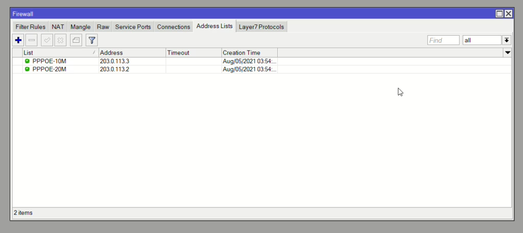
Address List
I’m using Address Lists to match and differentiate between speed allocations. One client is in the 10Mbps list and the other is in the 20Mbps. This means additional clients can be added to the address list without additional Mangle Rules per client.
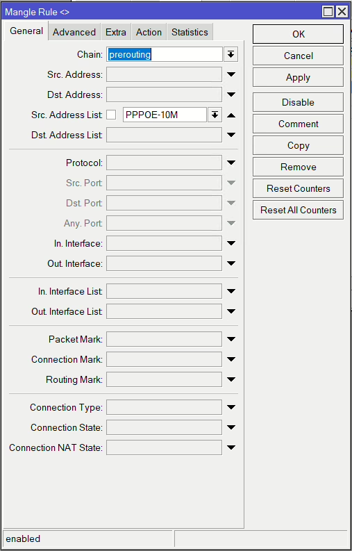
Mangle Rules (Upload)
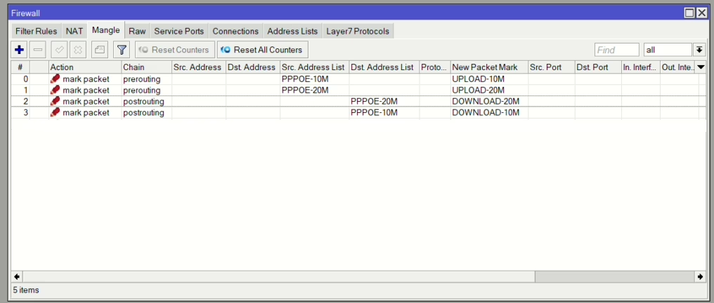
There will be 2 mangle rules per service (Upload and Download) so for our example 4 rules (2 x 10Mbps and 2 x 20Mbps).
Start with upload, using Chain as prerouting and Src Address list. Then under Action mark the packet with unique Upload mark for the speed allocation (UPLOAD-10M). Repeat for the 20Mbps rule.

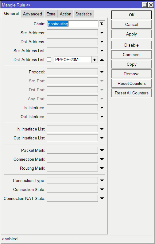
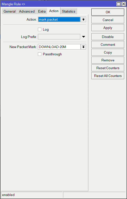
Mangle Rules (Download)
Now do the same for the Download, using postrouting as the Chain and Dst Address List. Then, use DOWNLOAD-20M as the packet mark (assuming this is the 20Mbps service).
Once complete there will be the four
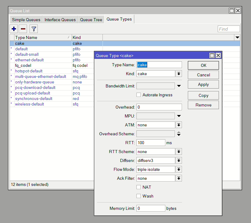
Queue Type
Now to build the Queues, we start by adding the Queue Type (Queues > Type). We are using CAKE for our demo but as mentioned before, to see more about how to configure this check out the CAKE guide.
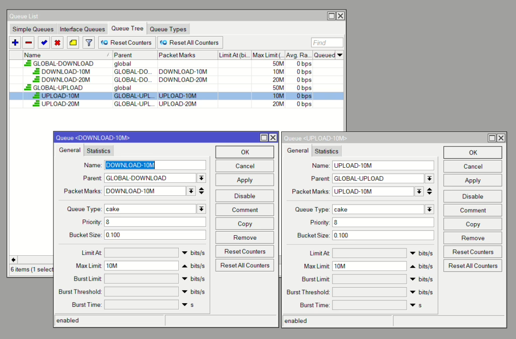
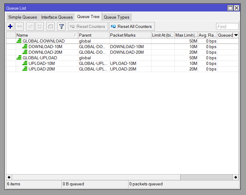
Queue Tree
Now to build the Queue Trees, I have a Global Upload and Download to allow additional Queues outside of these connections if needed in the future. These are using default queue types and set to 50Mbps.
Then we add an Upload and Download Queue using the Global one as the parent for each speed. We select the relevant parket marks from the mangle rules and Queue Type as Cake we added before. The speeds are bits/s so add M or G for Mbps or Gbps.
Now we can test loading the connections and testing latency-sensitive data streams such as Voice or Gaming. For more information on this check out this video:


